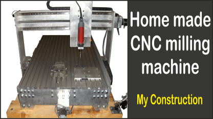
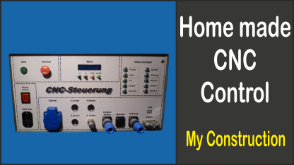
Here I describe the construction of my self developed CNC control for controlling my milling machine (part 1 of 2).
Table of contents
Requirements
My requirements for the electronics were:- 4 axes (but first only 3 axes are used)
- Switchable spindle and cooling
- Microstep (electronically switchable)
- USB port
- Limit switches to prevent the further drive on the hardware side (not only by the software)
- Three selectable modes of operation:
- PC (Control of the milling machine by the software)
- External (Control of the milling machine via an external port for possible future expansion)
- Manuelly (Control by hand → switching off the phase currents)
- Display with menu selection
- Input for length sensor
- Various LEDs
Basic implementation
After a little thinking about how to realise my wishes, I decided on the following principle [German]:
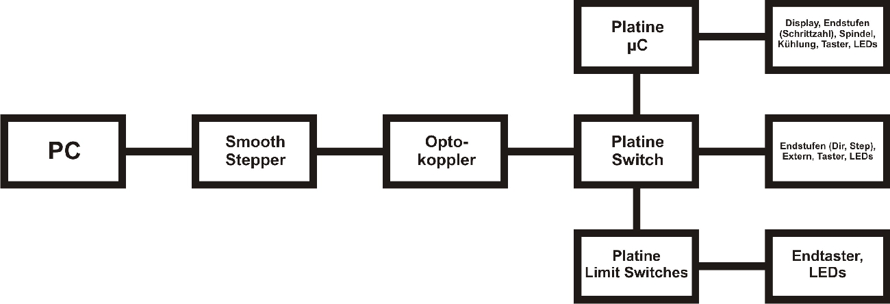
I connect the PC via a USB port on the SmoothStepper, which converts the commands to the parallel port.
Short note:
Some of you will undoubtedly think now, why I didn't just bought a standard USB → parallel converter for little money. At the beginning I thought that too, but after long research I came to the conclusion, that this will not work, because such a converter is integrated with a USB driver in Windows, but the milling software requires direct access to the interface. The SmoothStepper is quite expensive, but unfortunately there aren't many alternatives if you want to have a USB port. However, the SmoothStepper does only work with the software "Mach3", as far as I know.
Behind the SmoothStepper there is a opto-board to separate the PC galvanically from the controller. The opto-board is then connected with my three self-designed circuit boards, where all IO-elements can be connected.
Control boards
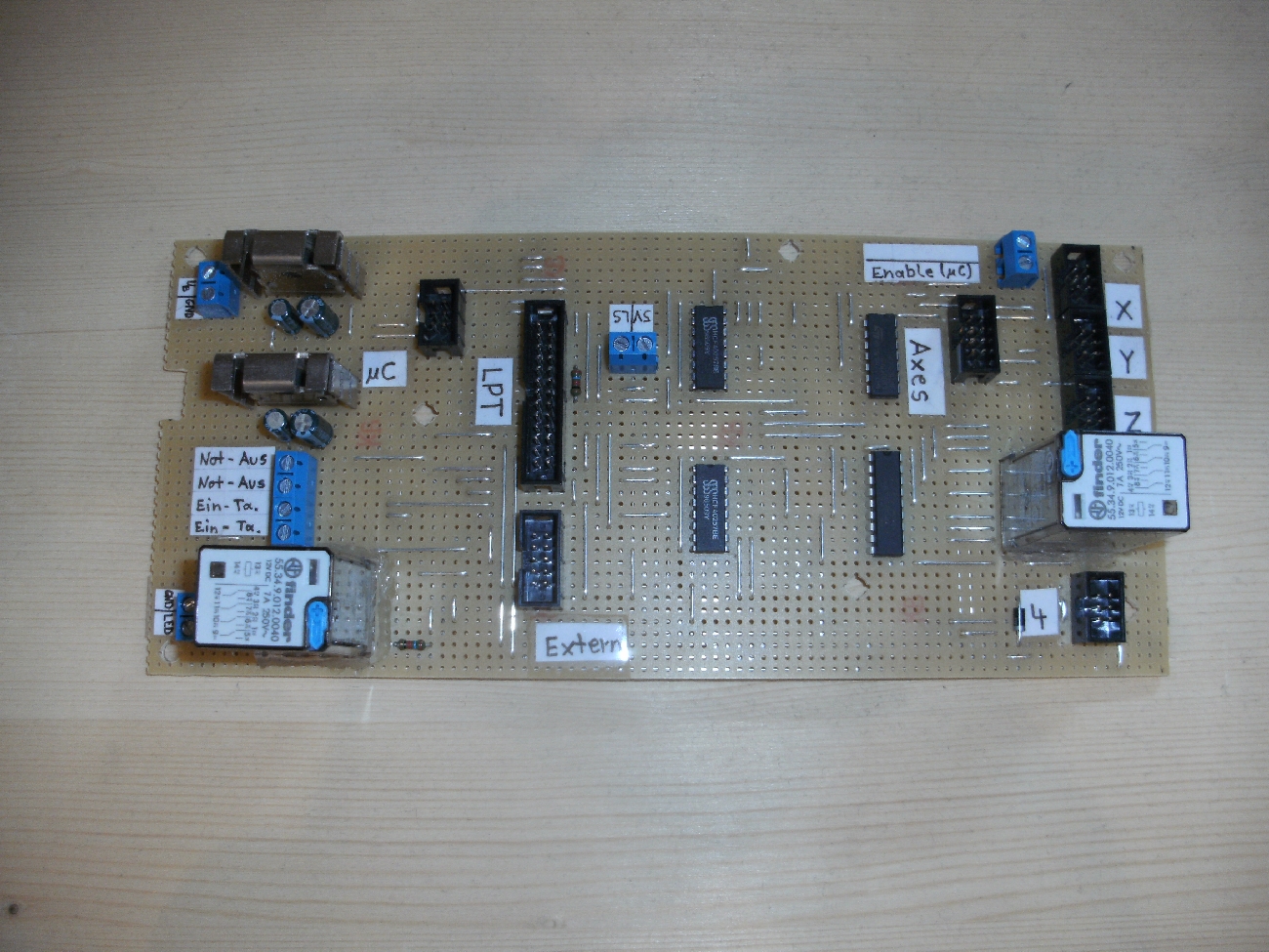
Circuit board "Switch"
This circuit board has the following main tasks:- Central interface where the boards "µC" and "Limit Switches (Axes)" are connected
- Switching between PC and external signal source
- Emergency stop
- Connection to the output stages


Here you can download the circuit diagram in PDF format: Circuit diagram: board "Switch" [German]
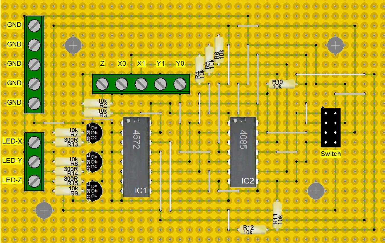
Circuit board "Limit Switches (Axes)"
The main tasks of this circuit board are:- Connection of limit switches
- Prevent the further drive of the axes on the hardware side, when limit switch is active


Here you can download the circuit diagram in PDF format: Circuit diagram: board "Limit-Switches (Axes)" [German]
Circuit board "µC"
The main tasks of this circuit board are:- Control of the menu selection (display)
- Control of the relays for spindle and cooling
- Generating the signal for the multiplexer of the board "Switch"
- Setting the number of steps of the output stages


Here you can download the circuit diagram in PDF format: Circuit diagram: board "µC" [German]
Output stages
Of course, I bought the micro-step output stages because building it on myself would be too time consuming. At these output stages, you can set the number of steps using DIP switches. However, I would like to adjust the number of steps electronically with the microcontroller. So I had to disassemble the output stages and solder a flat cable parallel to the dip switches.


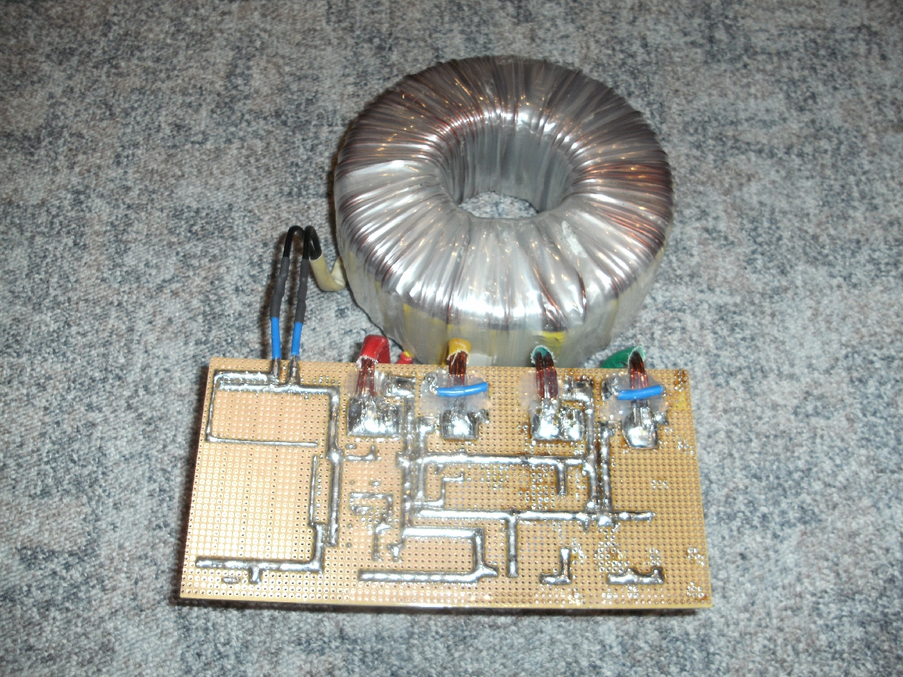
Power supply
I also had to build a current supply. So I bought a 800VA toroidal transformer for little money; of course it is absolutely over-sized but who cares. Unfortunately, a toroidal transformer has the stupid characteristic to have a high starting current, so I also had to invent a circuit.
Here you can download the circuit diagram in PDF format: Circuit diagram: power supply [German]
That's the built-up circuit: