In this article I describe the construction of the mechanics of my self designed, computer controlled milling machine.
Table of contents
Why do I build a CNC milling machine?
When I was doing my projects, I came to the point, that certain things I simply could not realise. So it was clear that I needed a CNC milling machine.
Of course, it was no option to buy a milling machine because that would be very boring (wouldn't it?). I would show you the CAD drawing of my CNC milling machine but unfortunately it only exists in my head.
Aluminum profiles with linear bearings as basic construction
I decided to build the milling machine with aluminum profiles and aluminum plates.
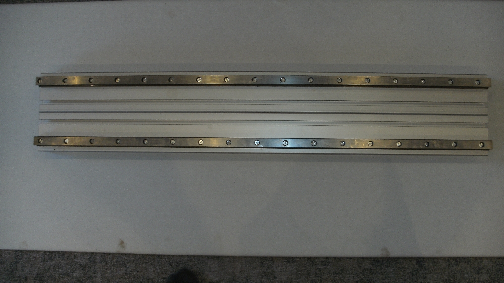
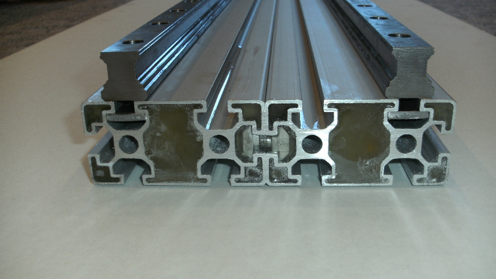
On the following pictures you can see the aluminum profiles that I completely filled with sand and sealed the ends with epoxy, so that the machine is more stable and has less vibration.


On these aluminium profiles I finally mounted linear bearings. Here you can see the Y-axis:
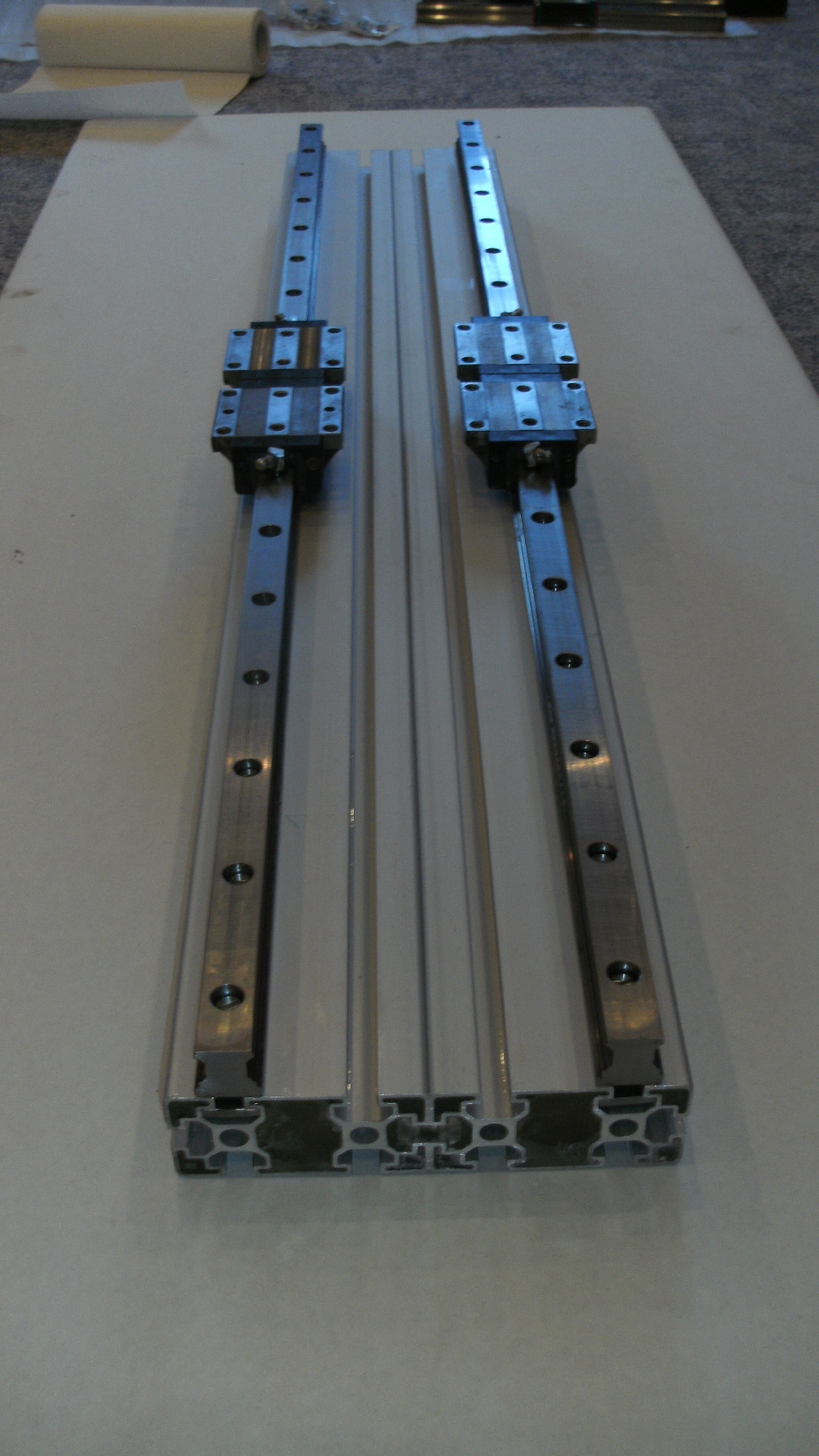
T-nuts are very expensive, so I decided to produce my own ones to mount the linear bearings. I bought flat steel, drilled holes and cut threads in it.


Construction of the basic frame
I did not have a milling machine at this time, so I had to handle all aluminum plates and profiles with file and saw. For the following two 15 mm thick aluminum plates, I needed a long time for sawing them with a jigsaw: 2 - 3 hours per plate.

Here you can see the final basic frame:


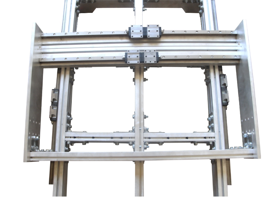
The entire frame has been screwed with solid angles. On the right picture you can see the Y-axis, which was not bolted to the base frame at that time.
Rotary ball spindles for high precision
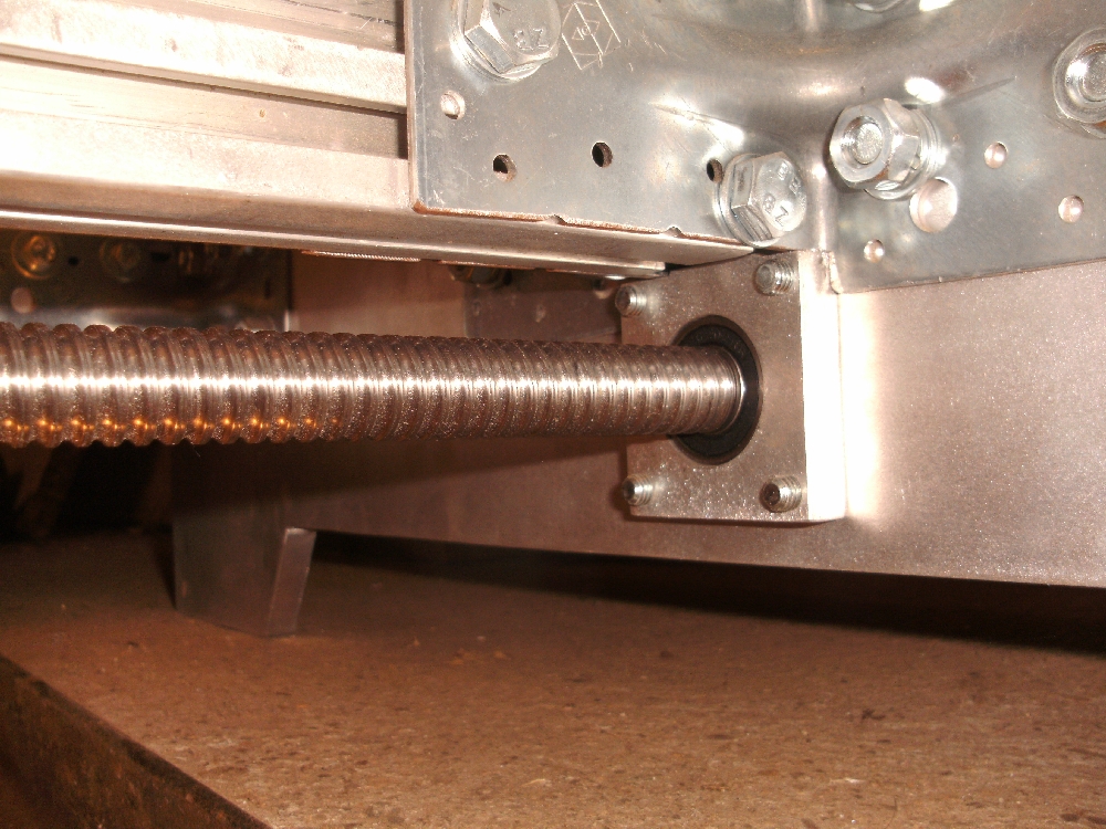
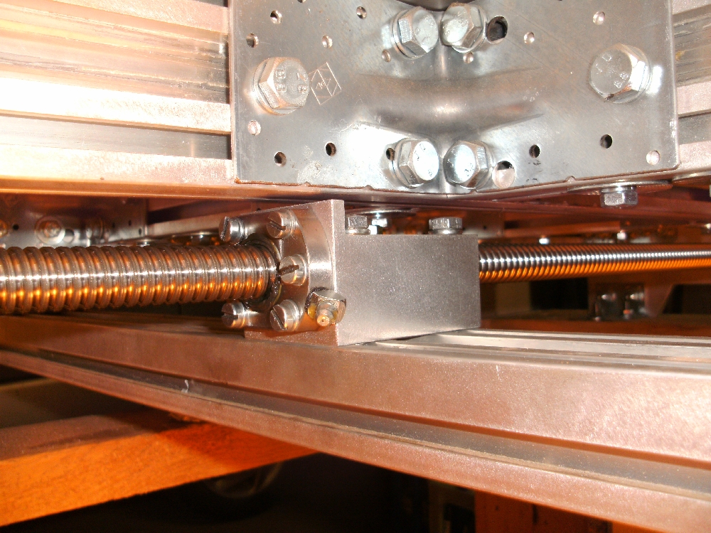
Because of the fact, that I mounted linear bearings, I also had to use rotary ball spindles. On the motor side the rotary ball spindles are mounted with fixed bearings (each constists of two angular ball bearings) and on the other side with floating bearings (each constists of one deep groove ball bearing).


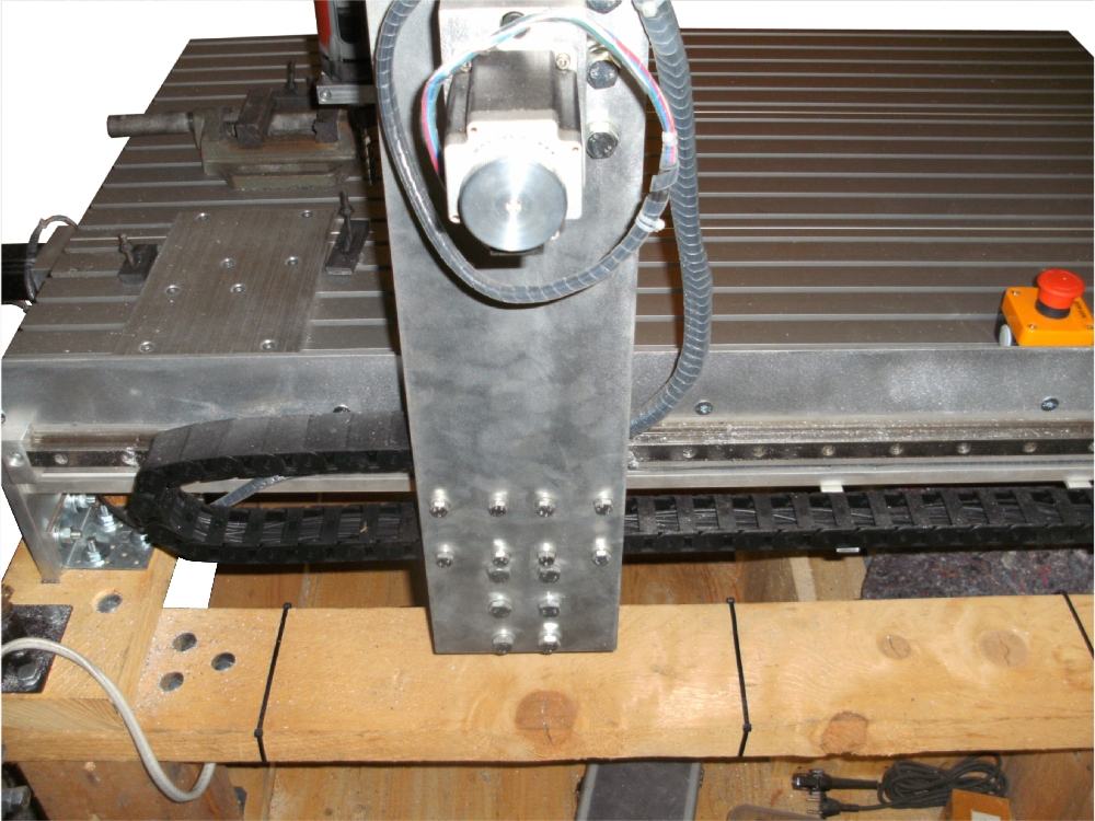
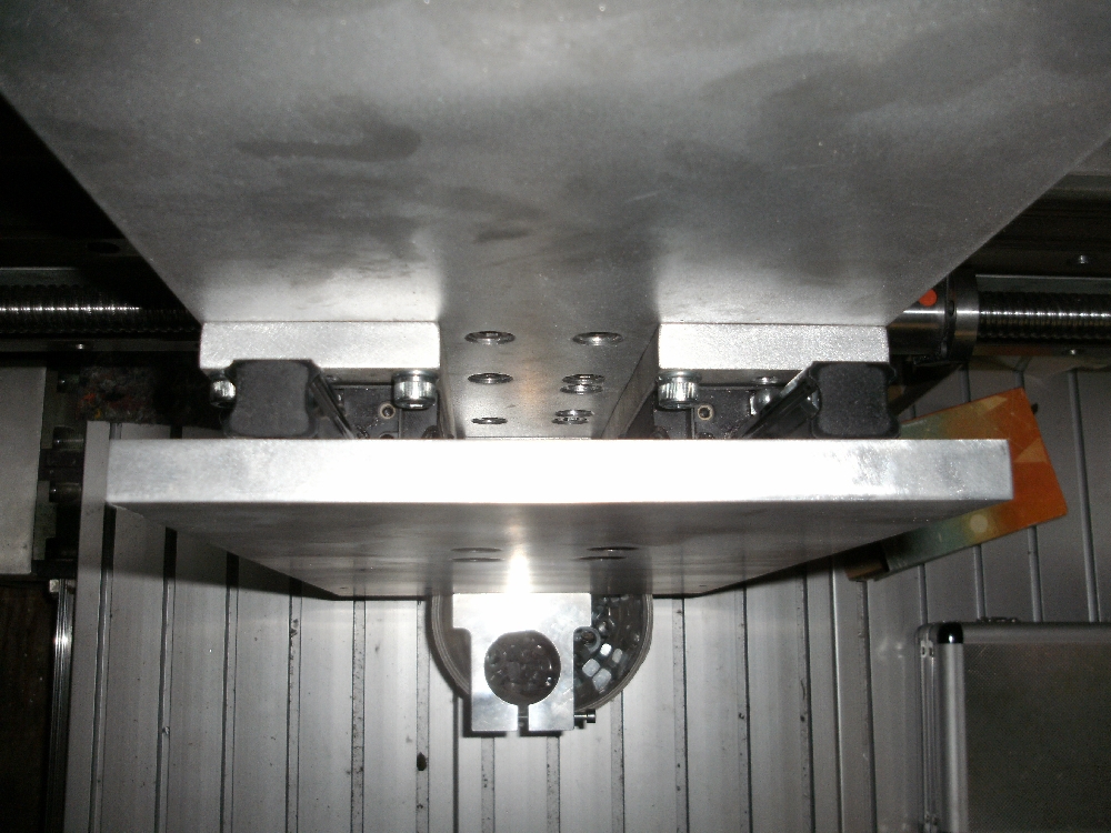
Construction of the Z-axis
The pictures of the Z-axis are not the best ones, but I think you can see the basic construction:


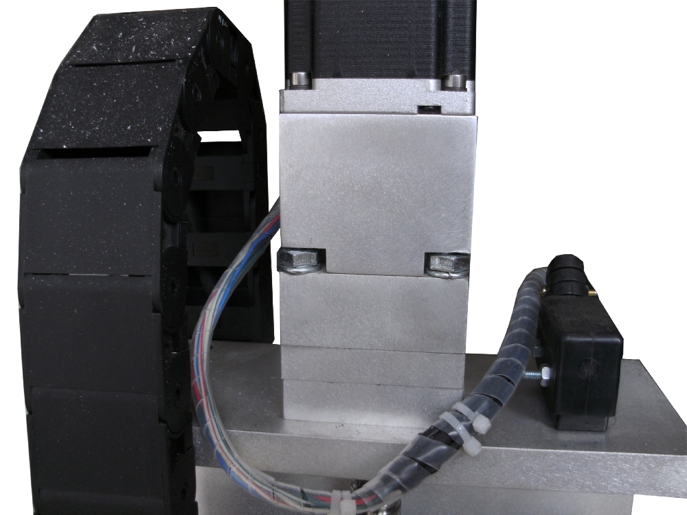
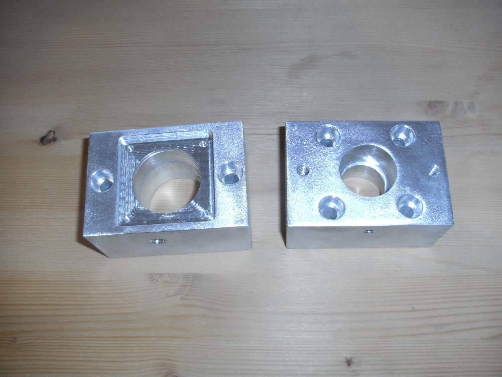
Motor
At the beginning, the motor (including the fixed bearing) was fixed with several aluminum plates, in which different-sized holes were drilled. Later, when I was finally able to mill, they were replaced by the machined aluminum blocks on the right picture. The engine has a torque of 3 Nm and a resolution of 200 steps per rotation. Running in the 16th step operation, there are 3200 steps per rotation.
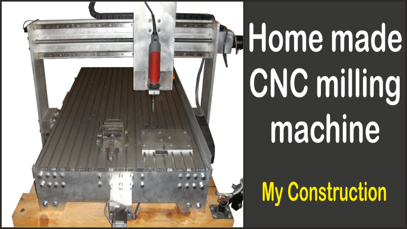
Final milling machine with laptop holder
Here you can see the final CNC milling machine:


Of course, I also mounted a suitable notebook holder...