At the end of my studies of Electrical Engineering I had to search for a suitable topic for my Bachelor's Thesis. Then one day I saw the perfect topic on a chair's website: "Development and construction of a microcontroller board test device".
Table of contents
Videos
Problem
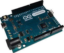
The problem is: there are courses, where the students can build hardware circuits with microcontroller boards and then they can program these boards. Sometimes the boards are connected incorrectly (e.g. if two outputs are connected together), which can destroy individual pins or the entire board. In addition, some boards are already damaged right after purchase. To avoid an unnecessarily long troubleshooting, a test device should be developed and build, so that you can test the boards for their full functionality. In this specific case, the microcontroller board Arduino Leonardo is used. The result of my bachelor thesis is basically a universal tester.
Requirements
The board tester should be developed to check the following things:
- Digital inputs
- Digital outputs
- Analog inputs
- Communication interfaces (I2C, SPI)
Furthermore, a report should be created after the test, in which all the test results are listed.
Hardware
Development
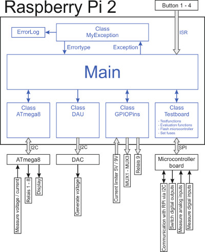
The tester is based on a Rasbperry Pi 2. The Pi is responsible for the programming of the microcontroller and for the basic control of the test. The basic structure of the tester looks like this:
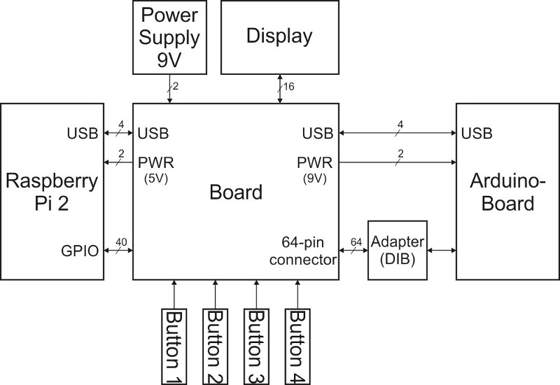
The test device was designed to support many microcontroller boards with the corresponding adapter and little software adjustments. In each case, the Arduino boards Uno, Mini, Pro Mini, Micro and Nano should be supported. The following minimum requirements have been observed:
- Generation of an analog voltage
- Analog-to-digital converter for measuring voltages
- Selection circuit for contacting different pins
- Circuit protection
- Current sensor
- Possibility of a continuity test
- Sufficient number of connection pins
Basic construction
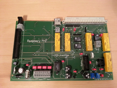
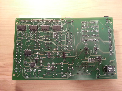
The developed and assembled board looks as follows:
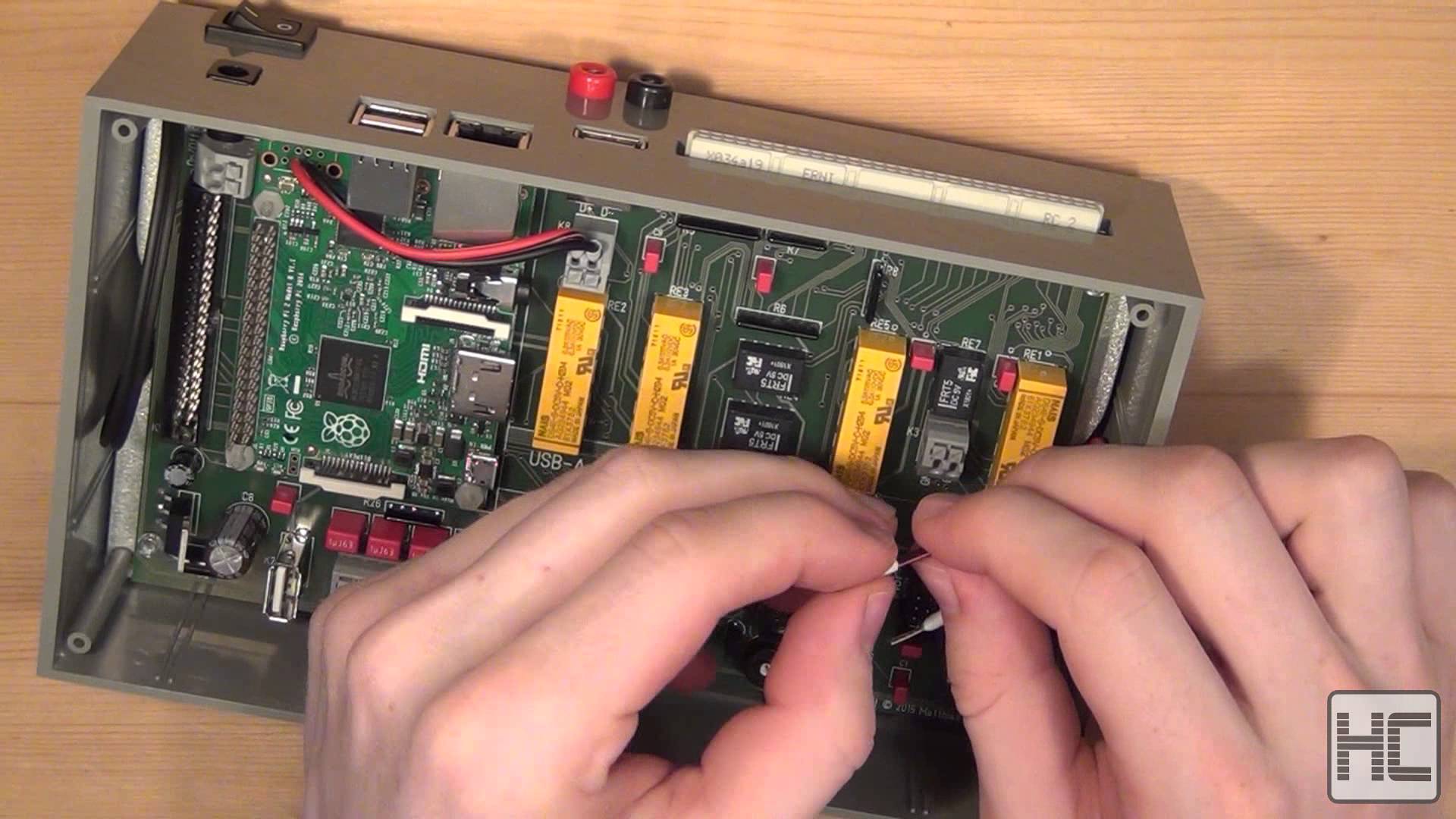
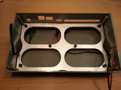
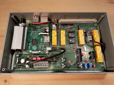
In the following pictures you can see the casing with the PCB holder and with the mounted electronics:
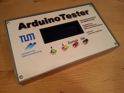
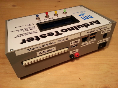
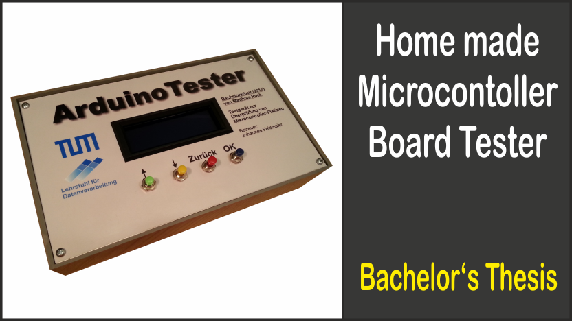
The final test device you can see at these two pictures:
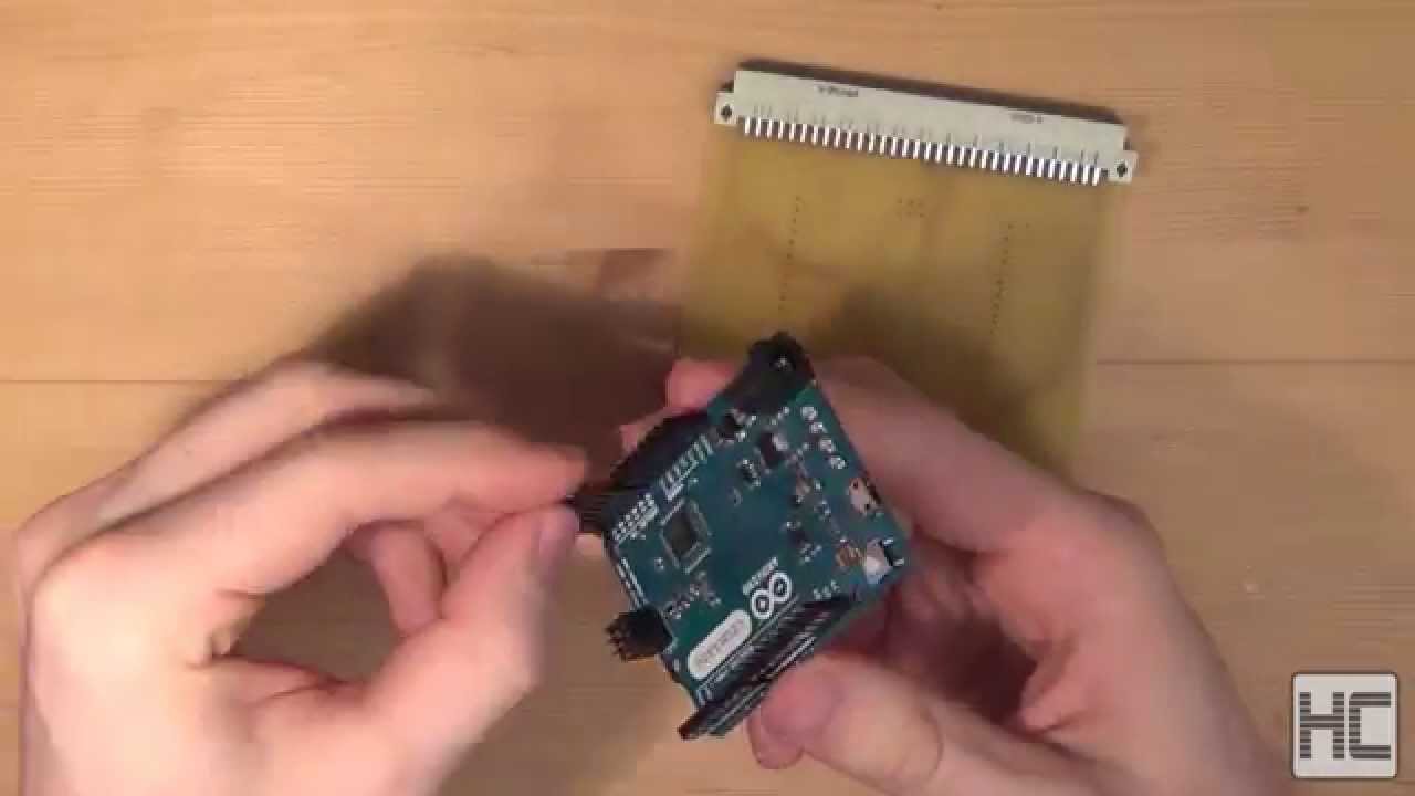
The following adapter is connected to the ArduinoTester, to test the microcontroller board Arduino Leonardo:
Software
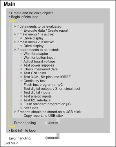
The basic structure of the software is shown in the left image. On the right side you can see the program flow:
Bachelor Thesis
Unfortunately, all the following files are only available in German!
The bachelor thesis, in which this project is described in detail, can be downloaded here:
Bachelor thesis: "Entwicklung eines Testgerätes zur Überprüfung von Mikrocontroller-Platinen"
All relevant files which are mentioned in the thesis, you can download here:
- DVD/Funktionstest - Reports/*
- DVD/Mechanik/Adapter Leonardo - Bilder.pdf
- DVD/Mechanik/Gehäuse_Ausfräsungen/*
- DVD/Mechanik/Gehäusedeckel/*
- DVD/Mechanik/Leonardo_Board-Remover/*
- DVD/Mechanik/Platinen-Halterung/*
- DVD/Mechanik/Testgerät - Bilder.pdf
- DVD/Platinen/*
- DVD/Schaltpläne/Adapterplatine_Leonardo - Schaltplan.pdf
- DVD/Schaltpläne/Testgerät - Schaltplan.pdf
- DVD/Stücklisten/*
- DVD/Software/ArduinoLeonardo/*
- DVD/Software/ATmega8/*
- DVD/Software/RaspberryPi/*
Modifications
Here you can see all changes (expansions / improvements) which were made. The modified files can also be downloaded.

