Here I describe the construction of my self developed CNC control for controlling my milling machine (part 2 of 2).
Table of contents
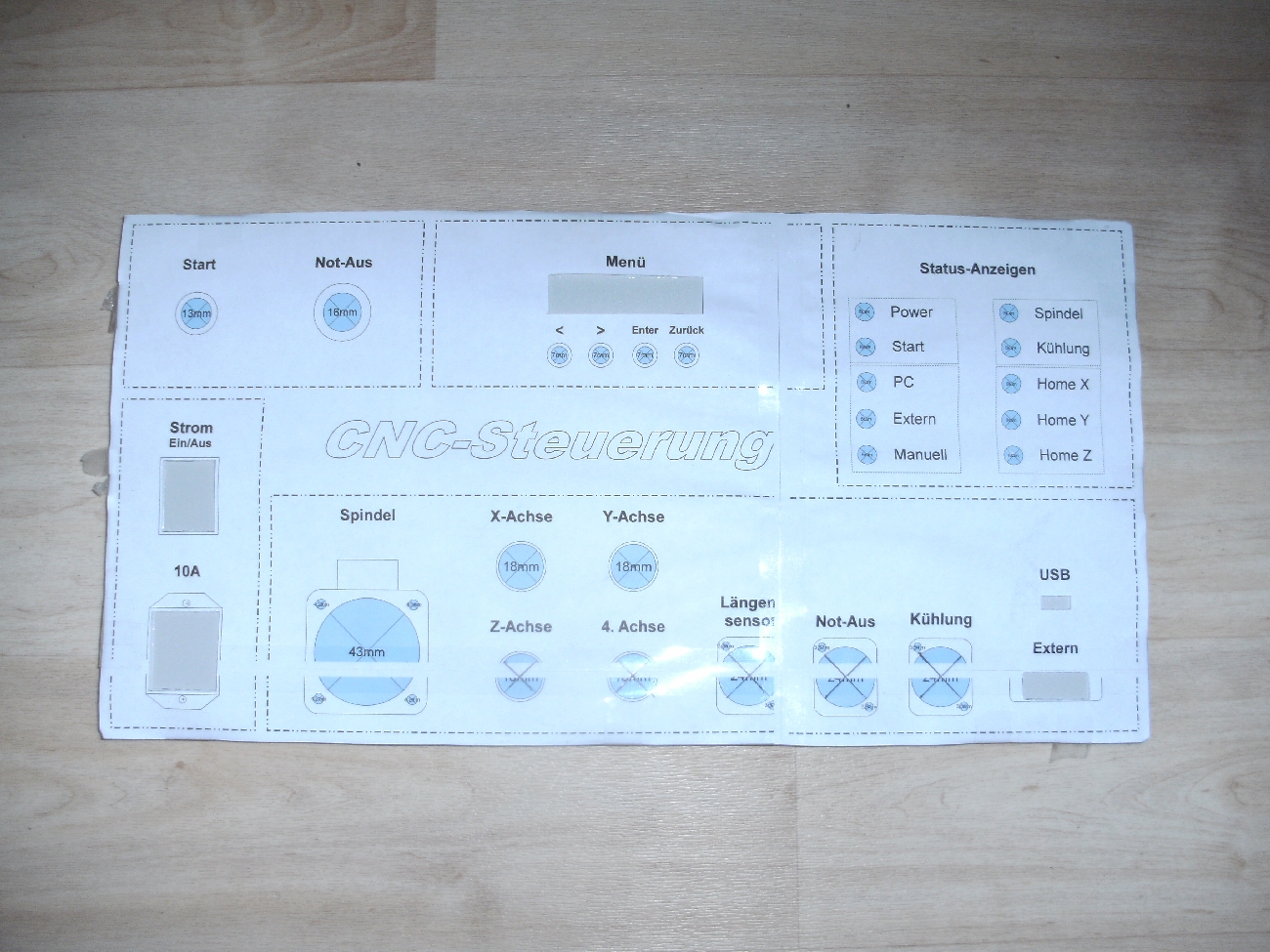
Casing
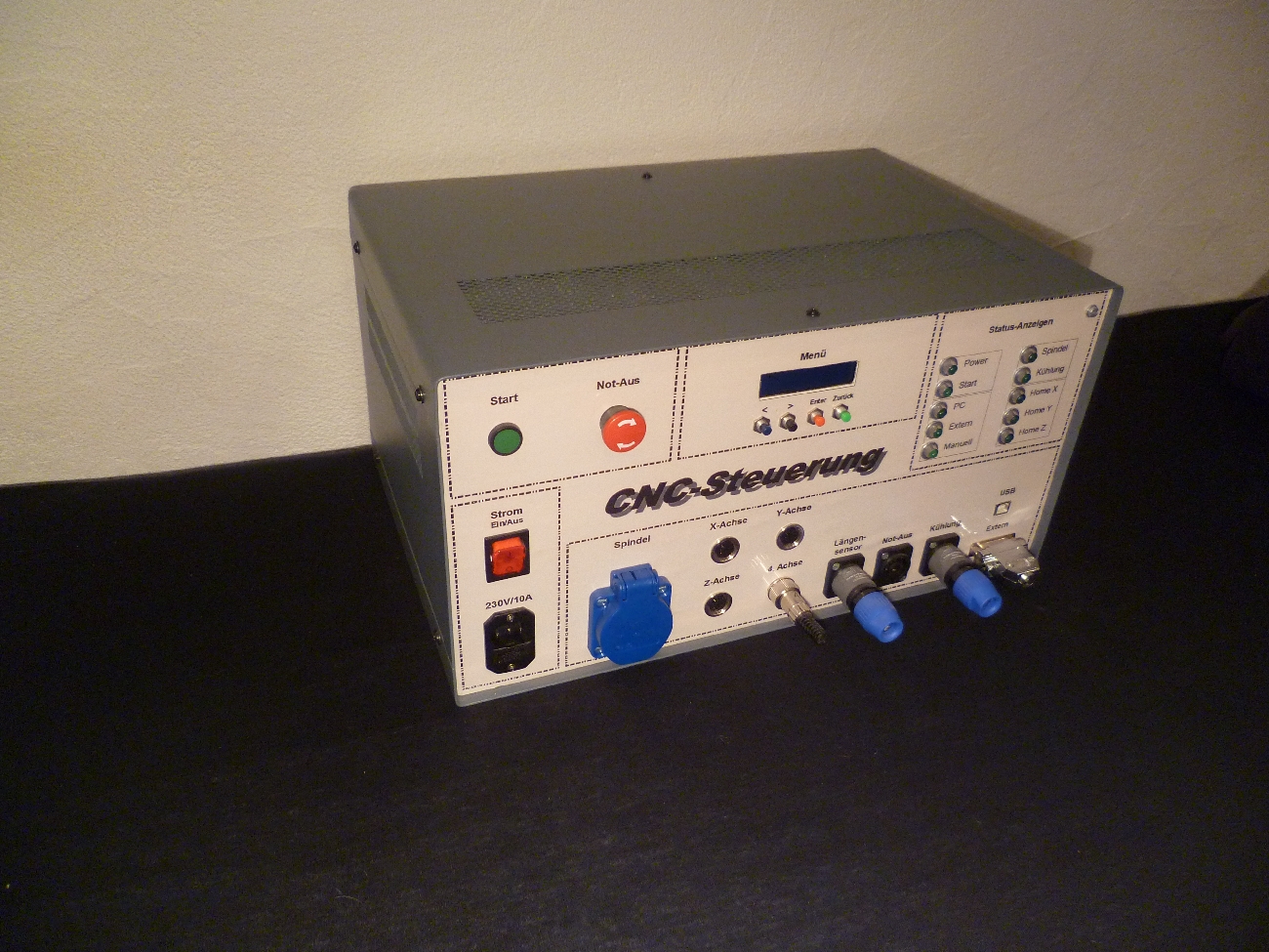
The whole electronic system was installed into a housing, which front panel I also designed and produced. The layout was created in "Open Office Draw" and printed by a photo shop (and then stuck on the front panel).


Installation of the electronics
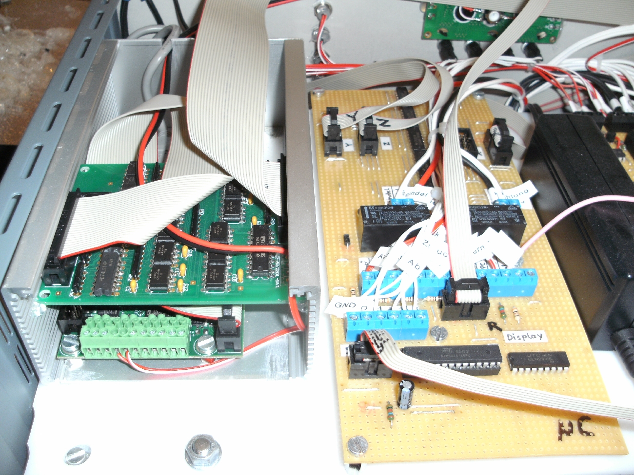
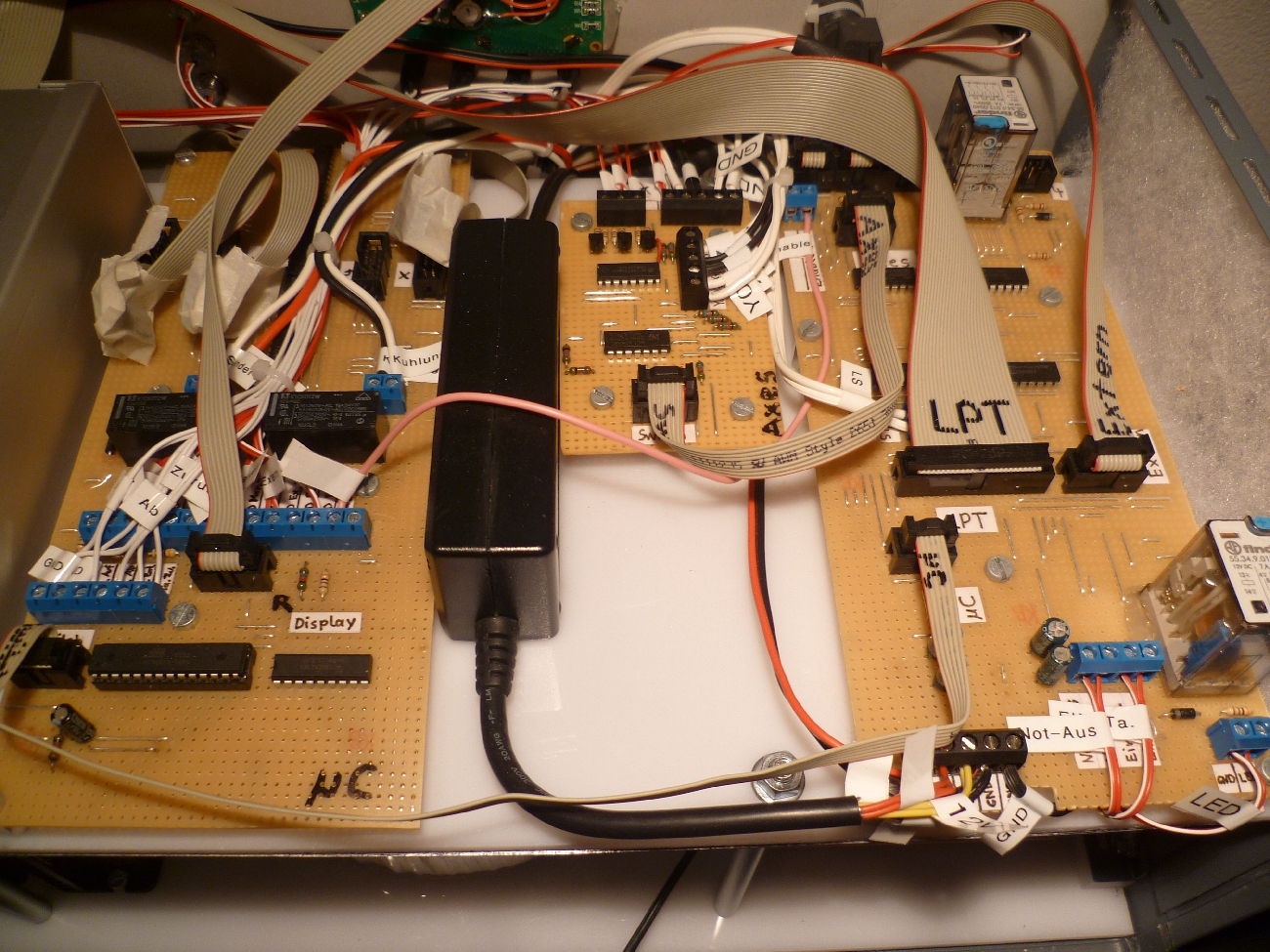
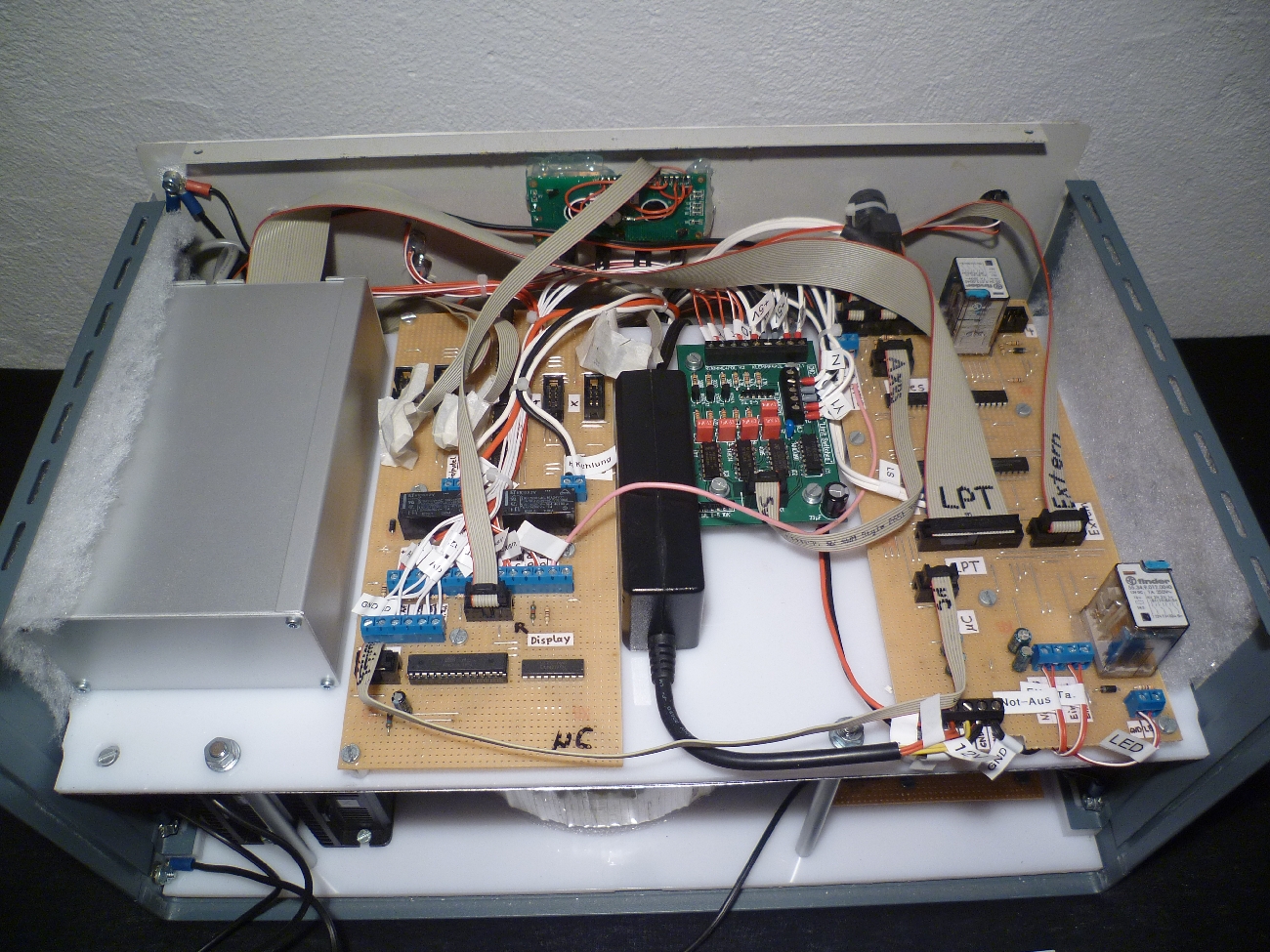
Here you can see the casing with the built-in electronics:
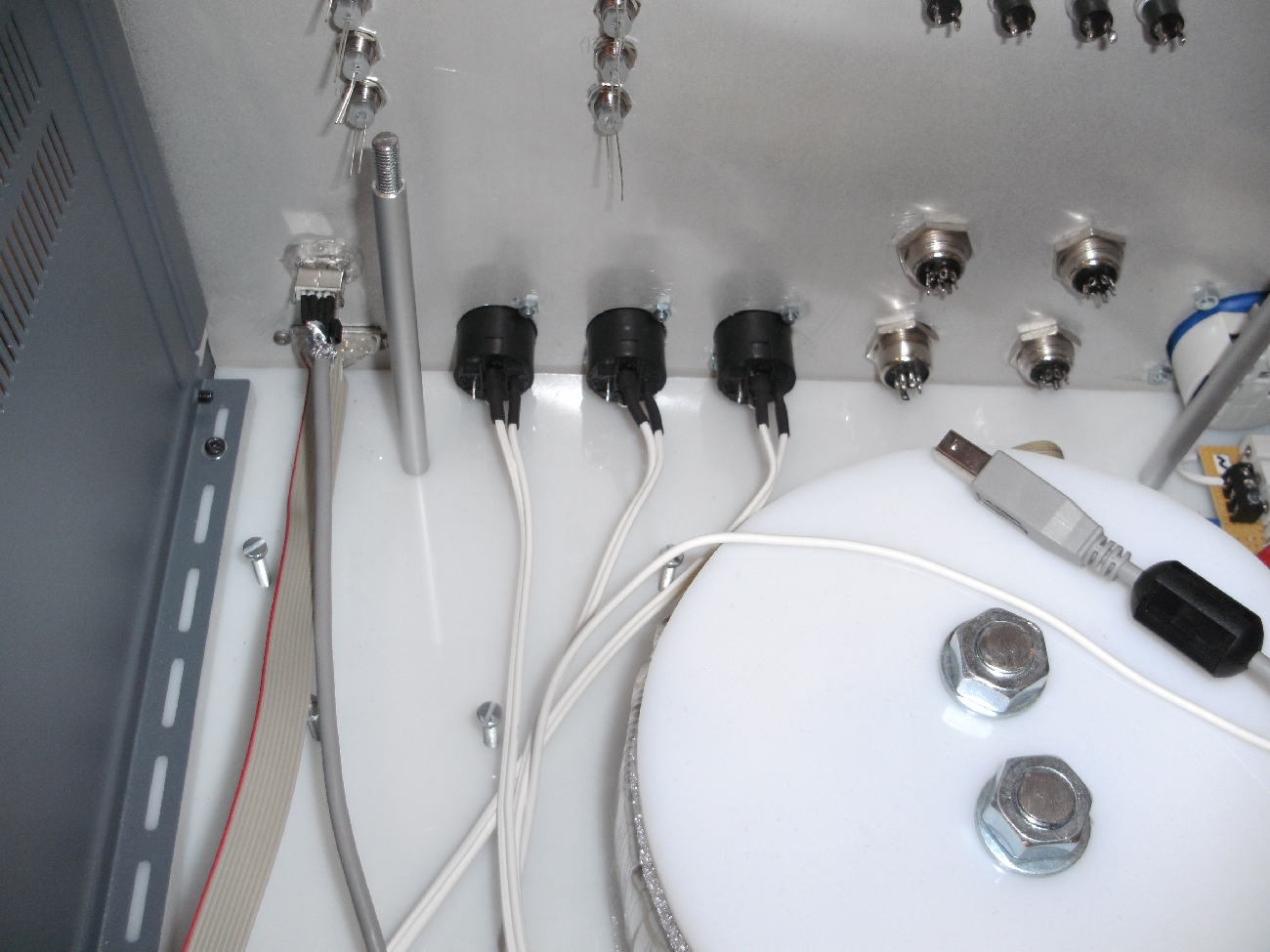
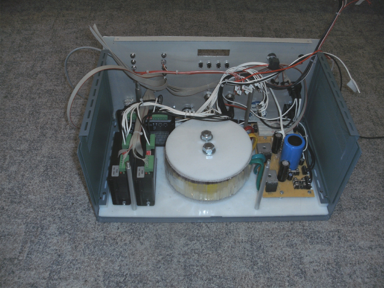
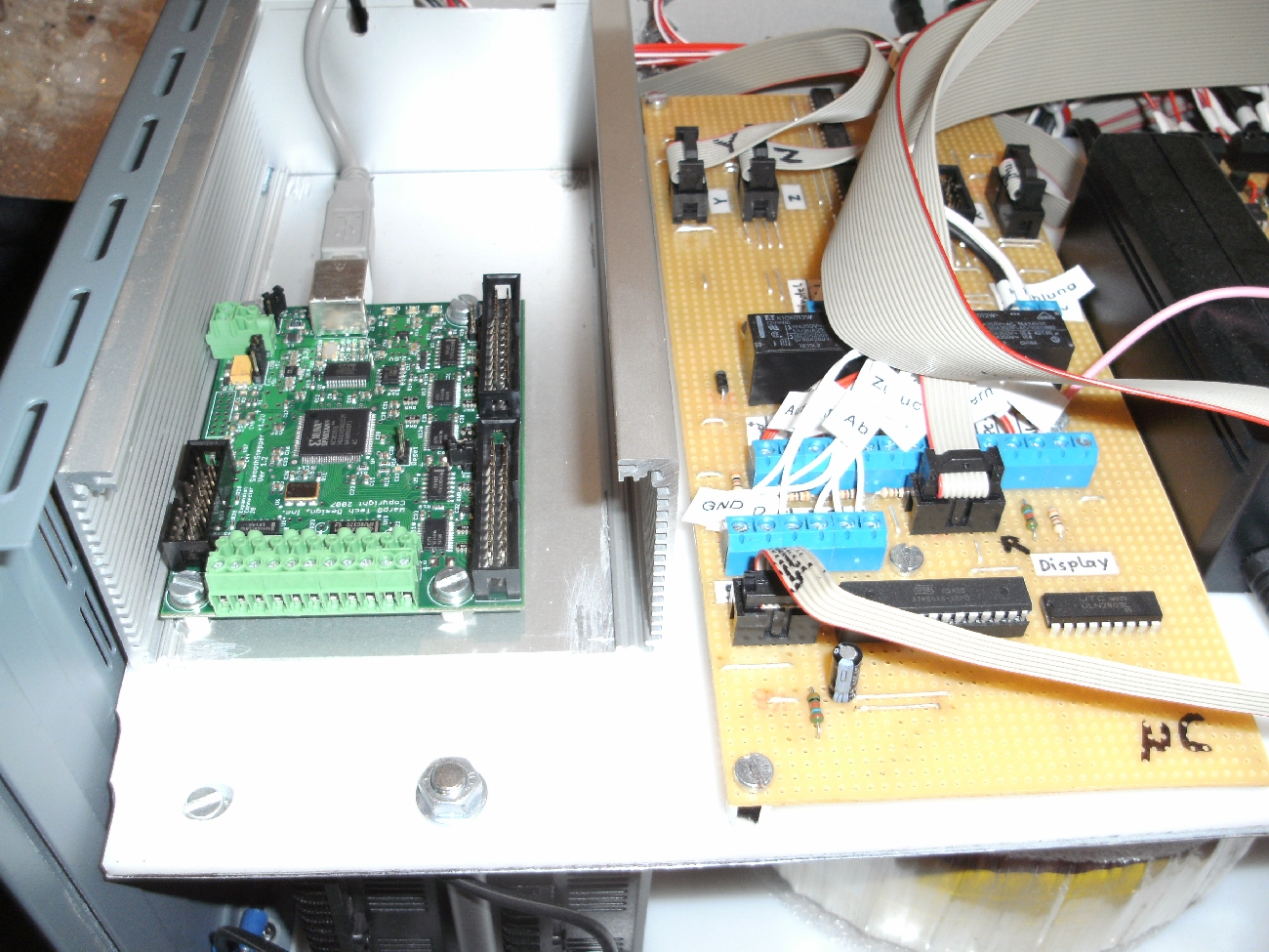
The board in the additional metal chassis is the SmoothStepper and that board above is the opto-board. I had to install the additional housing because the SmoothStepper is very susceptible to electromagnetic interference (for better shielding).

Final control
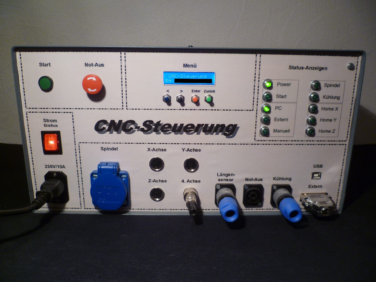
After the cover has been installed, the final control looks as follows:

Startup
1. test
When I switched on to control the very first time with open housing, the housing was not grounded and in the circuit many pullup-/pulldown resistors were missing.
The result:When I approached the control with my hand, the stepper motors started to vibrate and the whole control system has done pretty crazy.
In addition, the SmoothStepper reported an error within a few seconds.
1. modification
For the modification I had to remove the boards and integrate a variety of pull-up or pull-down resistors in the circuit. Additionally, all housing parts were grounded and the SmoothStepper was installed in an additional housing together with the opto-board.
2. test
Then the control was switched on again and at first sight everything was fine: no uncontrolled vibration of the engines and no crashes of the SmoothStepper after a few seconds.
However, the engines ran extremely rough and the moved distance was not the same with the set number of steps of the output stages (software was configured properly)
After much debugging I unplugged the flat cables of the output stages from the "µC" board and set the number of steps manually via DIP switches.
⇒ now the milling machine ran perfectly and the moved distance was also fine.
The reason that the electronic step adjustment does not work, is that the electronic components 4066 (analog switches) don't disable the switches in the off state properly.
Conclusion: Never use the IC 4066 again.
Basically the milling machine worked, but I noticed that the board "Limit Switches (Axes)" did not properly lock when a limit switch was pressed.
In addition, the software sometimes reported under heavy load of the spindle, that a limit switch was pressed (though in reality no switch was pressed).
Probably there were several reasons for this: first, the switches in the previous circuit were not debounced and secondly, there was apparently the problem in some electronic compontents, that the signal levels were not clear enough.
2. modification: new circuit board "Limit Switches"
To solve these problems, the circuit diagram of the board "Limit Switches (Axes)" had to be revised.
Here you can download the circuit diagram in PDF format: Circuit diagram: board "Limit Switches" [German]
Of course I used this opportunity to get away from the breadboards. With the program "Target 3001" I created a board and then the board was produced by a company:
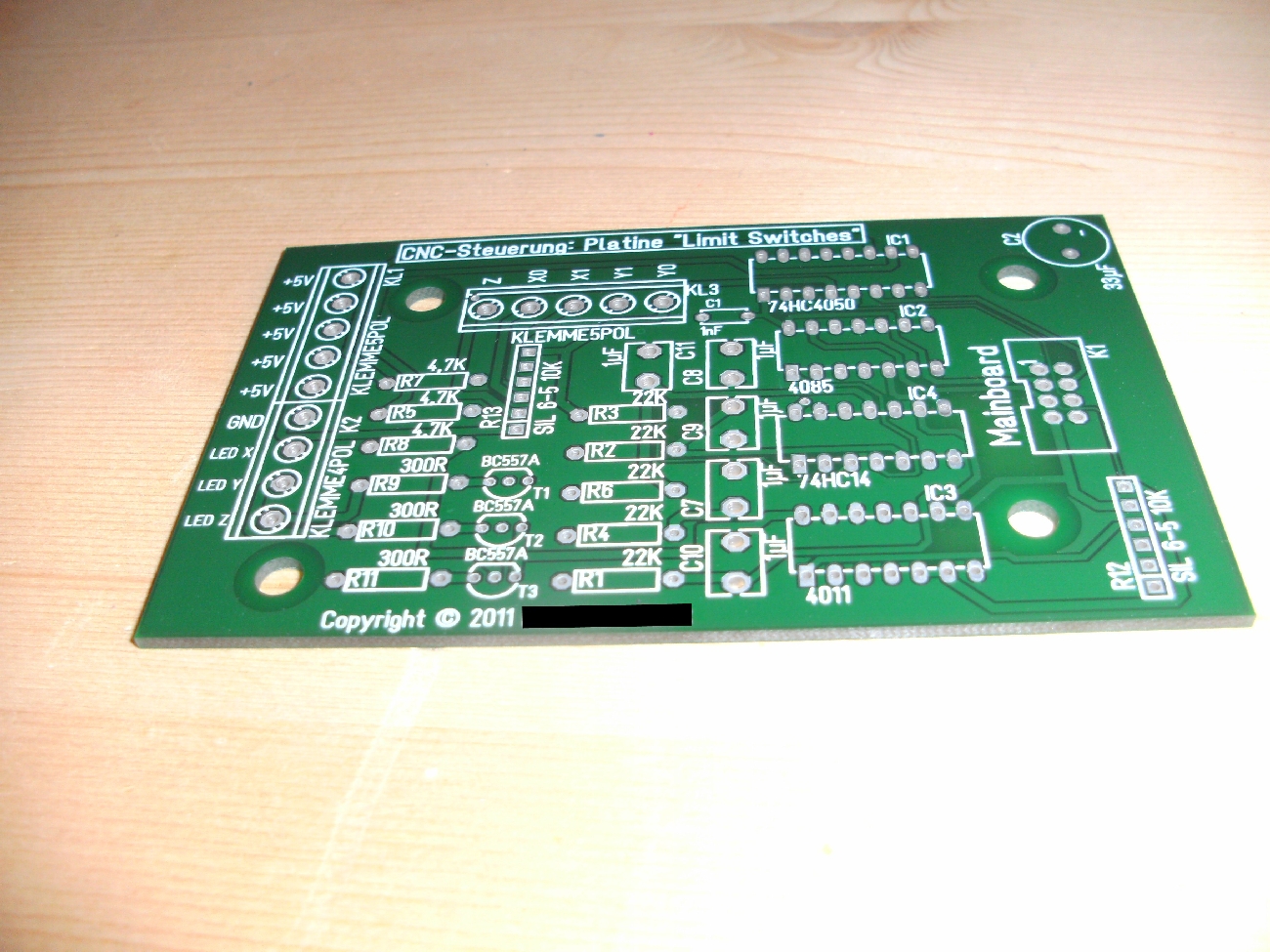
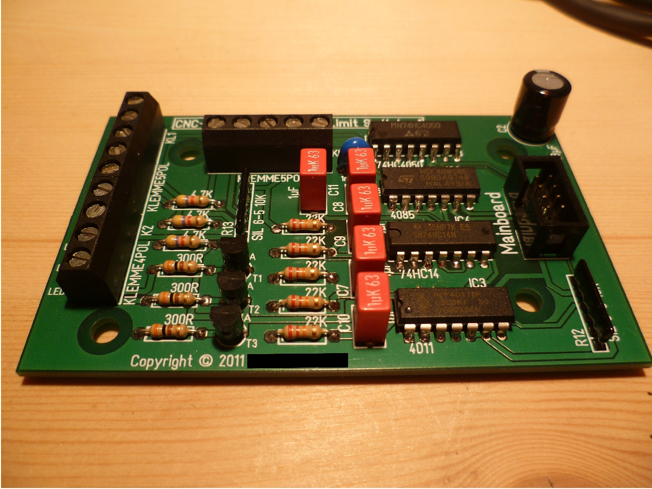

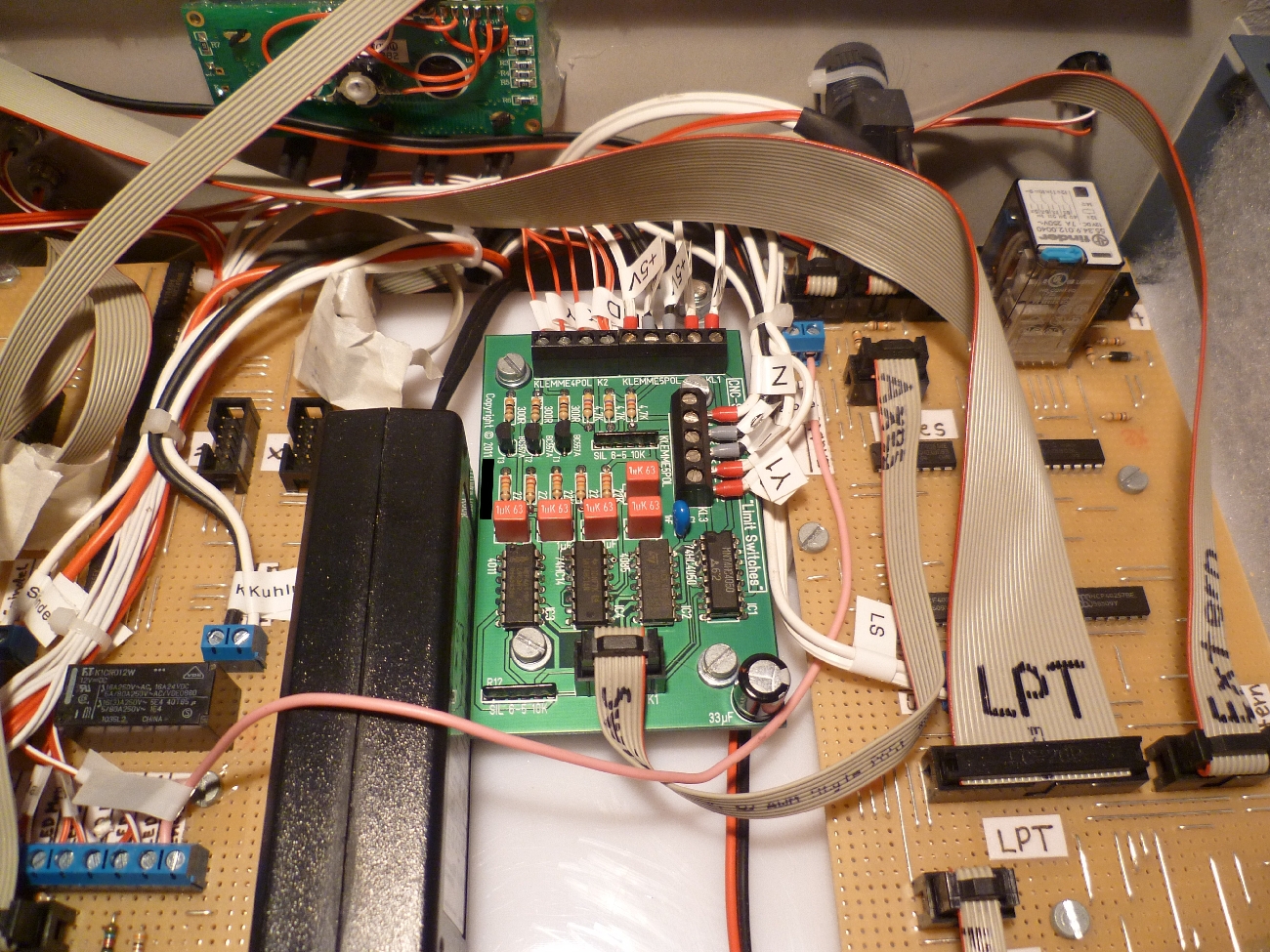
Built into the control it looks like this:
3. test
When I tested the new board "Limit Switches" I unfortunately realised that the limit switches no longer responded. So I tested the software and there was no signal change. So it was clear that there must be a bug on the board.
3. modification
And indeed, a resistor network on the board was not connected to ground but connected to +5 V (the circuit diagram was ok), so that no signal change could occur if a limit switch was pressed. Luckily, I only had to bend one pin from the resistor network to one side and solder it to the ground plane (which I scraped with a knife).

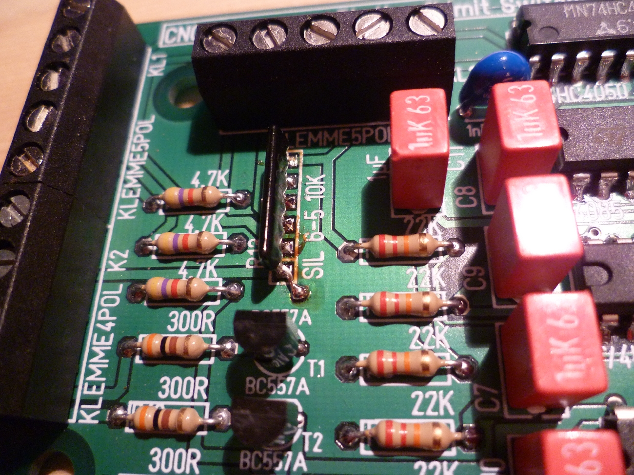
Finally, the circuit board works.
Remaining problems
| Problem | Possible reason | Possible solution |
|---|---|---|
| When the spindle is loaded heavily, the SmoothStepper sometimes crashes | Electro-magnetic interferences (EMI) | Better shielding |
| Electronic step adjustment does not work | IC 4066 of the board "µC" | Replacing the ICs by relays |