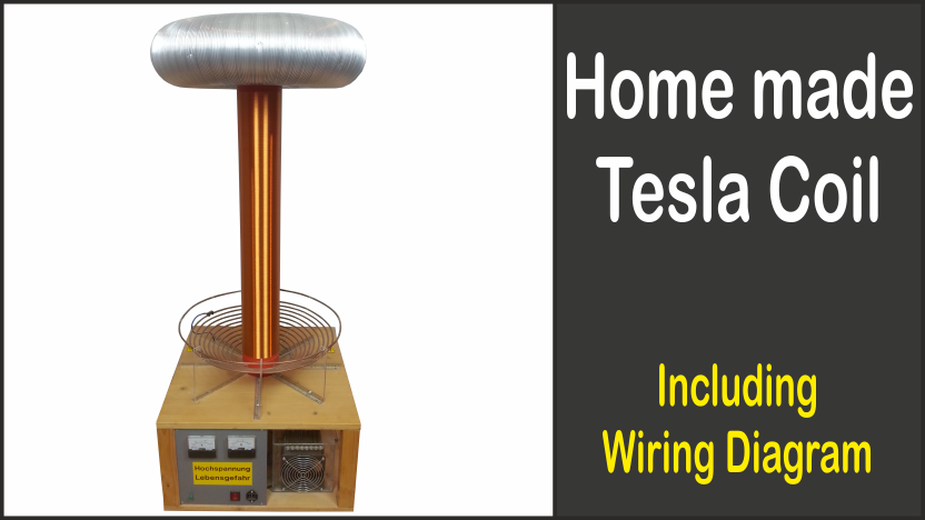
Tesla coils are very fascinating, because you can easily create lightnings with it. Originally, this coil was designed by Nikola Tesla to transmit energy wirelessly. However, since the whole thing did not work as expected, Tesla coils are now used for demonstration purposes only. Anyway, that was enough for me to decide to build a Tesla coil for myself.
Table of contents
Circuit diagram
Before you can start to build a Tesla coil, of course, you need a circuit diagram which is not very complicated. Unless you want to create music, which is also possible.
Here you can download the circuit diagram in PDF format: Circuit diagram: Tesla coil [German]
Data of the Tesla coil
The circuit diagram alone does not help anything because the individual components must be adjusted to each other. For the calculation this page [German] is quite helpful because there is a calculator for Tesla coils.
My data:
Primary coil
| Inner diameter: | 165 mm |
| Gap between windings: | 10 mm |
| Wire diameter: | 5 mm |
| Number of windings: | 9,4 |
| Winding angle (0 = horizontal, 90 = vertical): | 30 |
| Height above secondary coil beginning: | 0 |
| Outer diameter: | 41,9 cm |
| Coil height: | 7,5 cm |
| Wire length: | 8,6 m |
| Inductance (Wheeler): | 31 µH |
Power supply
| Output voltage: | 8 kV |
| Output current: | 50 mA |
| Maximum usable primary capacity: | 19,89 nF |
| Minimum possible frequency: | 202,5 kHz |
Secondary coil
| Coil diameter: | 110 mm |
| Gap between windings: | 0,06 mm |
| Wire diameter: | 0,6 mm |
| Winding length: | 735 mm |
| Size of the toroid (0 = sphere): | 125 mm |
| Outer diameter of the toroid: | 500 mm |
| Number of windings: | 1112 |
| Aspect ratio: | 6,6 |
| Inductance (Lundin): | 19,1 mH |
| Coupling factor: | 13,2 % |
| Wire length: | 387 m |
| Medhurst K: | 0,97 pF/cm |
| Self-capacitance: | 10,7 pF |
| Toroid-capacitance: | 22 pF |
| Resonance frequency without Toroid: | 351 kHz |
| Resonance frequency with Toroid: | 201 kHz |
| DC-resistance: | 23,5 Ohm |
| Resistance by skin effect: | 11,98 Ohm |
| Quality factor: | 681 |
| Required primary capacitance: | 20,2 nF |
Secondary coil
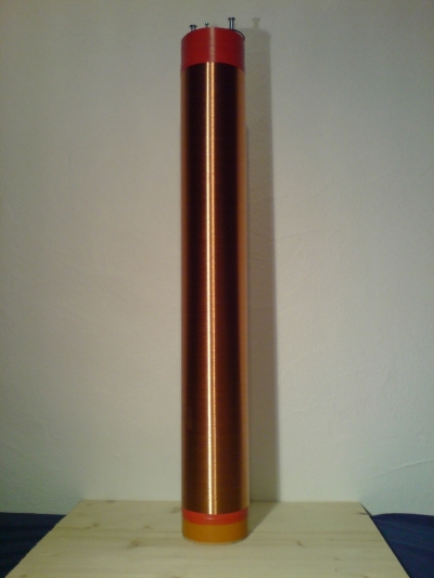
For the secondary coil, I needed a 387 meters long enameled copper wire. Such long wires you can buy on this page [German].
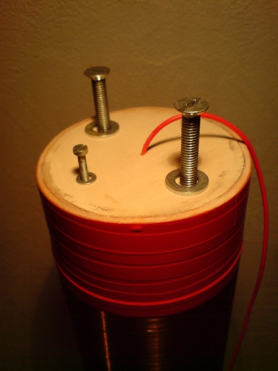
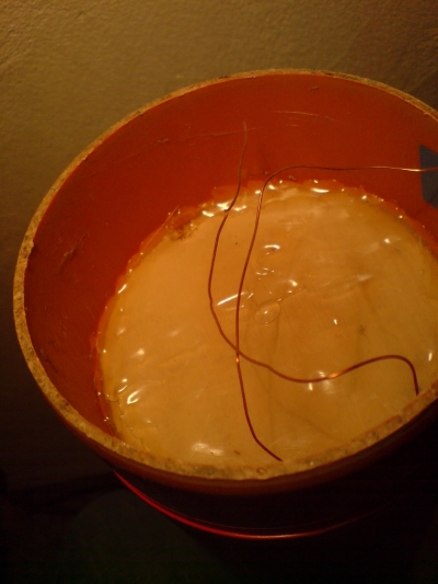
At the construction market I just bought a PVC tube and then I built a device with a cordless screwdriver with which I could let the tube rotate to wind the wire. Here you should ensure that there are no gaps between the individual windings and that there is no "overlap". For the 1100 turns I needed a few hours. Above and below, the wire was fixed with tape. With wood and hot glue I built "connections" for the ground plate and the toroid.
Toroid
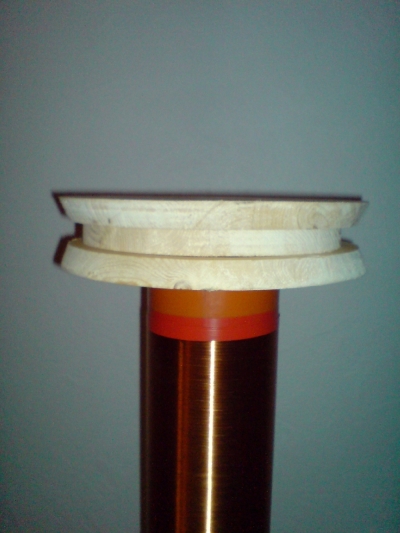
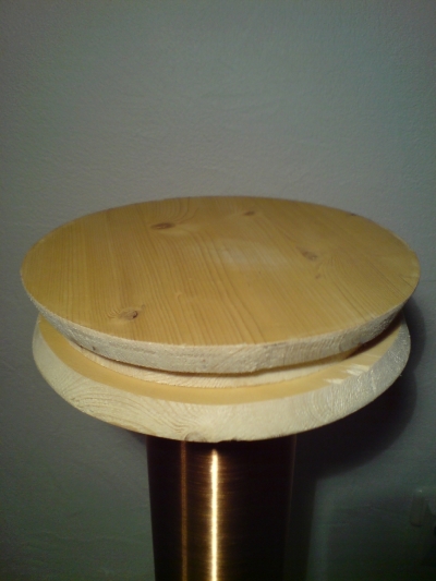
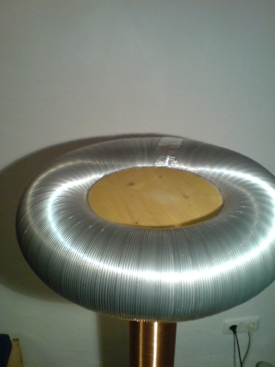
For the torus, I only had to saw out three wooden plates and then I glued a flexible aluminum tube around the outside with hot glue. The two ends of the flexible aluminum tube I glued together with aluminum tape.
Filter choke / safety spark gap
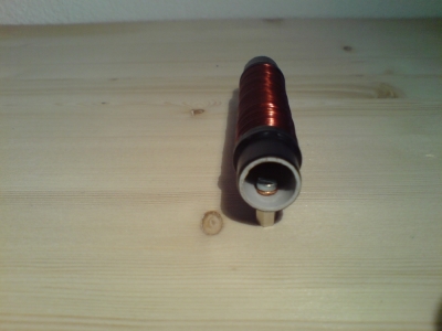
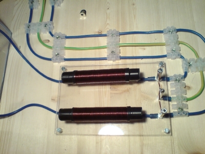
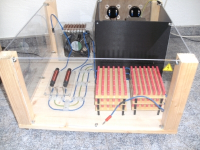
For the two filter chokes I have just taken a PVC pipe and wrapped an enameled copper wire around it.
On the right picture you can see the safety spark gap to the right of the filter chokes: these are just pieces of wire with air gaps in between.
Primary capacitor
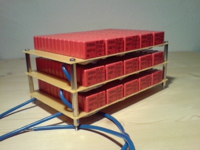
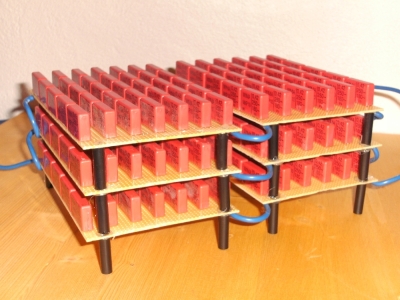
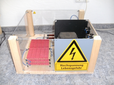
The primary capacitor consists of 195 MKP WIMA capacitors (420 nF, 180 V ~) which I soldered on breadboard. → 3x 65 pieces in series and the three then connected in parallel. → makes 20 nF at 11.7 kV voltage resistance. Actually, you should switch a high resistor in parallel with each capacitor to distribute the voltage really symmetrical, but I didn't do that.
First, I soldered the capacitors on three breadboards, but when I connected it to the transformer, there have been several sparkovers.
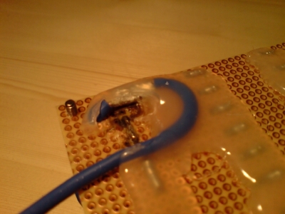
Subsequently, I removed several rows in between, distributed it to six breadboards, removed the pads in between and sealed it with hot glue.
Spark gap
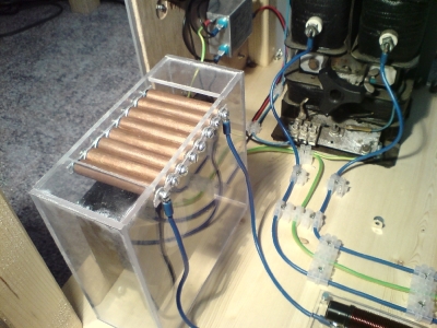
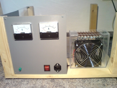
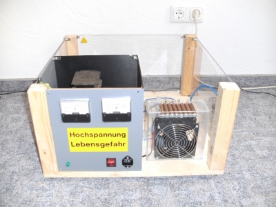
For the spark gap, I built a plexiglass casing that is so constructed, that the fan aspirates the air and blows it through the little gaps between the copper tubes. This should "break" the sparks faster.
Primary coil
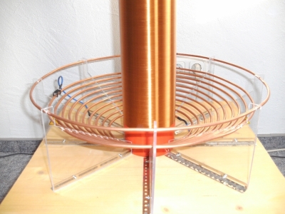
The construction of the primary coil was also very time consuming because I decided to build this in a 30° angle to the horizontal plane, and so it was very difficult to produce the holder made of plexiglass.
The adjustable tap, I realized with a simple fuse holder.
Transformer / power line filter
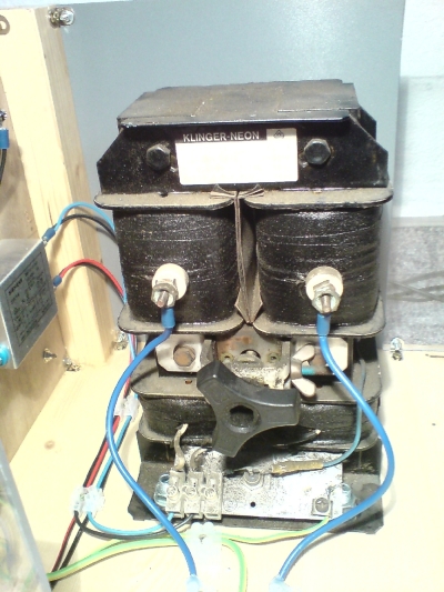
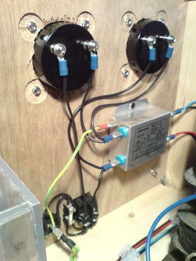
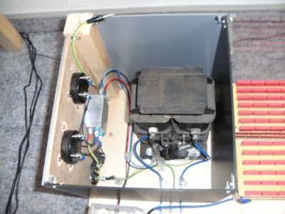
On the following pictures you can see the transformer and the power line filter. The transformer has 8 kV / 50 mA → 400 VA I would have prefered to use a transformer with double power but I didn't found a cheap one.
Final Tesla coil
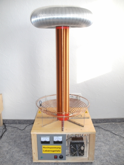
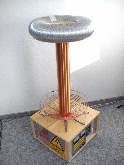
On the following pictures you can see the final Tesla coil:

